4:1
balun for 160 to 10 meters
By
Clay Wynn
|
Material:
Two T-80-2 Iron Powder Toroids, Red. (Oak
Hills Research, 10 for $3.60)
40 inches of blue 30 gauge wire wrap
wire. (Radio Shack-278-503)
40 inches of white 30 gauge wire wrap
wire. (RS-278-502)
BNC panel jack, or substitute your favorite
(RS-278-105)
Two binding posts, or substitute your
favorite, Pkg. of 4 (RS-274-661)
Enclosure 3 1/4" x 2 1/8" x 1 1/8", plenty
of room (RS-270-230)
|
Stack two
T-80-2 powdered iron toroid cores together. Use super glue,
or some other means to hold the two cores together. The powdered
iron cores should be tumbled smooth during manufacture so no protective
wrapping is necessary. You may want to wrap the cores with tape
to stabilize the wire during the winding operation. I did not use
tape but took extra care and time on the winding.
Using two colors of wire helps keep track of the connections after
winding. Wind 23 evenly spaced bifilar turns, white wire
parallel and adjacent to blue wire. That's 23 white turns,
23 blue turns, white and blue wound simultaneously. Leave
an approx. 4 inch tail at the start and finish of the windings.
Space the turns so that the distance on the core between the start
turn and the end turn is approx. 1/4 inch. Drill the holes and mount
the jack and binding posts on the enclosure.
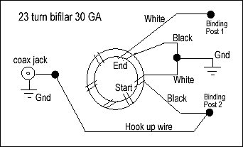
Cut short
and strip the white wire on the starting pair tail and the
blue wire on the ending pair tail. Leave enough to twist together,
and solder to a common ground strap. I used a 3 inch long piece
of solder wick braid for the ground strap. Any kind of hook up
wire will do. The wire wrap insulation is tough, so use an Exacto
knife or razor blade to strip the wire before soldering. Trim
to fit and solder the blue tail of the start turn to one of the
binding posts, likewise the white tail of the ending turn to the
other binding post. Take care not to nick the copper when stripping
the insulation.
Using a piece of insulated hook up wire, solder one end to the
center conductor of the BNC Jack, the other end to one of the
binding posts. Now one of the binding posts will share a connection
with the wire from the BNC center conductor and a wire from the
balun winding. The other end of the ground strap is soldered to
the shell of the BNC panel jack. Some ASCII art is attached that
shows the wiring connections. If the wiring arrangement is still
unclear, consult the literature on baluns.
After
dressing the leads, the balun is mechanically attached to
the side of the plastic box. I used a hot melt glue gun and the
clear elastomer sticks. I carefully placed the nozzle of the gun
in the center hole of the balun and built up an inverted mushroom
column of clear elastomer, slowly extracting the gun and feeding
the melt until flush with the top of the balun. Choose any technique
that best suits you. Simply packing the enclosure with scraps
of polyurethane foam sponge would probably work.
The size
of toroid core was chosen to allow the balun to be housed
in a pill bottle or a plastic 35mm film cannister, although this
involves a little more "ship-in-the-bottle" construction planning.
The toroid winding is self-shielding, so practically any material
for the enclosure will do. Powdered iron vs. ferrite is a little
more forgiving if you forget and dump 100 watts through the QRP
balun like I have been known to do.
If you use an all metal enclosure, additional care must be taken
to insulate the binding posts from the metal. Insulating washers
are provided with the RS parts. One problem with plastic material
is that parts mounted solely with a threaded shell and one nut,
like the BNC jack, eventually will loosen. This may be an important
consideration for field rugged equipment.
A number
of experiments were done with different wire size, insulation
thickness, number of turns, and number of cores to arrive at the
above configuration. 23 turns are not that critical. Somewhere
between 21 - 24 turns will suffice.
Performance of the balun is good from 160 to 10 meters. I've used
it up to 10 watts carrier power with good power transfer and no
detectable core heating. Computed ohmic losses are less than 50
milliwatts at 5 watts input. The balun and enclosure assembly
specified will fit in a shirt pocket and weighs 2 oz.

|


![]()


![]()