|

Construction
of impedance matcher
The
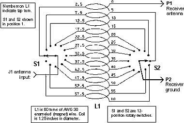
circuit has three parts, a coil, which you must fabricate
yourself and two commercial rotary switches to vary the input
and output impedances. Twelve-position rotary switches (Radio
Shack part number 275-1385) are used on the input (antenna side)
and on the output (receiver side). The antenna is connected to
the wiper of the input switch and the 12 poles are connected to
taps along the coil. The wiper of the output switch is connected
to the receiver ground (the outer sleeve of either external antenna
jack). The 12 poles of the output switch are connected to different
taps along the coil. Turn 0 on the coil is connected to the whip
antenna. The table shows the exact tap connections.
|
Switch
Pole
Number
|
Antenna
Switch
Coil Turn
|
Receiver
Switch
Coil Turn
|
|
1
|
2.5
|
5
|
|
2
|
7.5
|
10
|
|
3
|
12.5
|
15
|
|
4
|
17.5
|
20
|
|
5
|
22.5
|
25
|
|
6
|
27.5
|
30
|
|
7
|
32.5
|
35
|
|
8
|
37.5
|
40
|
|
9
|
42.5
|
45
|
|
10
|
47.5
|
50
|
|
11
|
52.5
|
55
|
|
12
|
57.2
|
60
|
The coil is
60 turns of AWG 30 copper enameled wire. Turns are wound tightly
in a single layer. The coil has an approximate diameter of 1 1/4
inches. I used an old plastic 35-mm film can as a coil form. Taps
are made every 2 1/2 turns as you wind the coil, stripping away
about 1/8-inch of the enamel insulation and soldering a 3 or 4-inch
connecting wire for eventual connection to the switches. I used
the AWG 30 copper enameled wire for the taps to reduce the bulk
and stress on the solder connections.
The switches come with a tab which prevents 360 degree rotation.
This should be bent out of the way to permit full rotation and facilitate
operation. The switches should be mounted on either side of the
coil in a small project box. I used a phone jack for the antenna
input. The output leads for the antenna and ground should be kept
separated from one another and as short as possible - no more than
8 inches. Alligator clips can be used to connect each lead to the
receiver. I fabricated a special clip to grip the swivel base of
the whip antenna. The ground connection is tricky. You don't want
to use a standard phono plug, as that will switch the contacts inside
the jack and cause problems. You only need to make contact with
the outer sleeve, so a sawed off phono plug might work well. If
you are using a dipole antenna or any antenna requiring a ground
connection the input ground can be made to the receiver ground inside
the coupler box.
|


