The
"Hula Loop"
Medium Wave DX Antenna
By
Sean Gilbert
HCDX Special,
April 2002
Updated
January 2003
The
concept of the "Hula Loop" came after many years of building medium
wave loops of varying size, shape and performance. Usually these
loops are constructed on a square wooden frame, with wire being
wrapped around the periphery. There are a few disadvantages to this
method of construction:
- The weight of the frame itself means that either it has to
be floor mounted, or else some form of support needs to be constructed
to enable the loop to be rotated without being physically lifted
each time.
- Wooden frames tend to flex when moved and can change size
dependant on the climate which can make the windings loose or
become too tight. This is quite a problem if you need to pick
the loop up to rotate it.
- The constructional difficulty of a wooden frame, making joints
and drilling holes or cutting slots can be off-putting for someone
who, like me, is not into Do-It-Yourself. To make a wooden frame
is fairly easy, to make a good wooden frame is NOT. I sought
an easier alternative that would give me a loop of a reasonable
size that could be easily rotated, was cheap and easy to construct
and gave good DX performance.
Thus the
Hula Loop was born.
CONSTRUCTION
DETAILS
The Loop Framework.
For the loop construction, I used 2 plastic children’s hula hoops
(purchased for about 2 US Dollars each).
The windings were made from multi strand hook up wire (single
strand could be used).
For the cross and down supports, 2 lengths of thin bamboo cane
were used. These are fixed to the control box with thin bolts
and nuts.
First of all we need to make the frame.
If you use 2 of the hoops joined end to end to form a larger hoop,
the diameter can be up to about 5 feet which was a little too
large for this location. I trimmed one of the loops down until
the overall diameter was just over 4 feet. These hoops come with
an in line joiner, so no glue is needed, which makes things even
easier!
Attackhing the Cross Braces. Now we need to attach the
cross brace support. Take a length of bamboo cane and measure
across the widest part of the loop, Cut the bamboo cane so that
it will fit across the widest part of the loop snugly and without
distorting the frame.
Next the cross brace needs to be secured to the frame itself.
Cut a small square through the outside of the plastic frame (where
the cross brace meets the side), so that a screw can pass through.
Repeat on the opposite side.
Use a small self tapping screw and gently screw through the inner
of the plastic frame and into the end of the bamboo cane. Do not
over tighten! A drop of glue may be needed to secure the mount,
although mine was fine without.
Repeat for the other side.
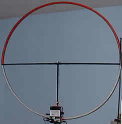
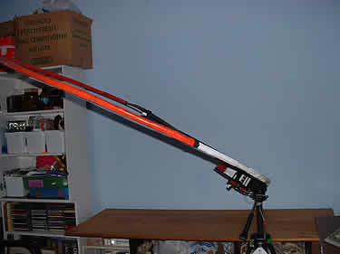
To form the rest of the "T" mount (refer to the main photo), take
a second length of bamboo cane, and measure so that you have about
10-15cm protruding at the bottom. How you attach the cane to the
cross member is up to you, my method was to drill a small hole
through the canes and use a thin nut and bolt (with large washers,
so the cane doesn’t split when the nut is tightened) to attach
the tops together.
For the bottom, I did the same except that the bolt passed through
the plastic frame. I used metal hardware but purists would recommend
the use of nylon. Personally I have not noticed any disadvantages
by using metal.
Making The Loop Rotatable.
Tilting
the loop is simple.
I had previously
used a discarded monitor base and a jack plug/socket arrangement
for rotation which worked very well but I soon found that it had
limitations and was inconvenient as the loop had to be raised
off the ground in order to reach the controls.
The
new method is to mount the loop and control box onto a camera
tripod by screwing the ‘shoe’ into the base of the control box.
This gives a secure mount that allows full rotation AND tilt.
With this arrangement I can tilt the loop from vertical through
to horizontal, which can give a much deeper null on some signals.
This also allows me to position the loop at a convenient height
so the controls are within easy reach.
The Main Winding. Having made the loop frame, the next
thing to do is to attach the main winding.
This is normally the part that causes most problems but if you
follow this method it should be fairly straightforward:
Tape one end of the hook-up wire to the bottom of the loop (wherever
you decide the bottom will be), leaving about 30cm free for connecting
to the tuning capacitor. Make sure you put a few turns of tape
(electrical PVC type tape is fine) to firmly secure the end.
Slowly feed the loop through your hand while keeping the wire
fairly tight and wind on to the loop. Secure the wire every 30cm
or so with a single turn of tape (ensuring that the wire is kept
tight against the loop).
Keep doing this until you have laid 5 complete turns on the loop
frame.
When you reach the end of the 5th turn, secure with a few turns
of tape and leave another 30cm length for connection to the tuning
capacitor.
At this point it is worth marking the two ends of the winding
as "MAIN", because the coupling turn will be wound over the top
of this winding and, unless you use a different colour wire, the
two could get confused when you are ready to connect everything
together! This comes from bitter experience!
The Coupling Loop. The coupling loop is a single complete
turn and is what will connect to your receiver. Wind the coupling
loop in exactly the same manner as the main winding, again leaving
30cm tails. Mark this one "COUPLING".
The reason for using a coupling turn instead of connecting the
main winding directly to the receiver is that a coupling turn
acts like a 5:1 step down transformer and provides a much better
impedance match to the receiver than would be possible if the
main turn were connected directly. This improved impedance match
allows a more efficient transfer of signal from antenna to receiver.
Using a coupling loop does have other advantages, i.e. the tuning
range is unaffected by the receiver input impedance and the "Q"
of the loop (sharpness of tuning) is not reduced, as would be
the case if the receiver were connected directly across the main
loop/tuning capacitor assembly.
The two free ends of the coupling loop should be connected to
a length of feeder terminated in a plug suitable for your receivers
antenna socket.
You can use twin wire (Bell wire) or coaxial cable for the feeder.
I have used 50 ohm coaxial feeder with my loop and have not noticed
any degradation in signal/directivity compared to twin "balanced"
feeder.
If you intend to use the FET amplifier, make this connection temporary
as the output from the loop will connect into the amplifier, and
so needs to be much shorter. The output from the amplifier would
then connect to your receiver.
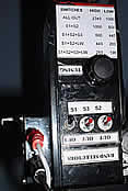
Attaching The Tuning Capacitor Network.
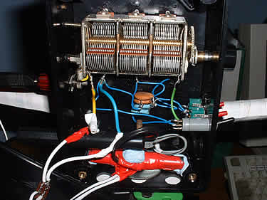
The tuning
capacitor network.
The tuning
capacitor is placed in parallel across the main winding and will
not be physically connected to the receiver or amplifier. The
tuning capacitor is what brings the loop alive. It is possible
to use almost any type of variable capacitor, but my preference
is for the old style air spaced variables that were found in older
radios.
These
capacitors normally have 2 or 3 "gangs" or sections, which can
be joined together to increase capacitance.
For my loop I used a 3 gang capacitor of unknown value. I would
recommend using at least a 2 gang type, preferably of 250pf per
section, or more.
To add flexibility to the tuning, I put switches in so that I
could use 1, 2 or all 3 of the gangs on my capacitor. Additionally
I added 2000pf of fixed capacitance through another switch, which
extended the tuning range down to 360kHz.
The extra capacitors are added in parallel, which increases capacitance,
thereby lowering the resonant frequency of the loop.
The tuning range of the loop will depend on the value of the capacitors
and to a certain extent the way the main winding was wound.
In the picture, the red tube at the bottom of the control box
is a MW ferrite rod and coil assembly from a discarded portable
radio. Switching this in series with the main winding allows the
tuning to extend down to 196kHz.
Sensitivity is not as great at lower frequencies, so the pre amp
really helps.
CONNECTING
AND TESTING
Now that the
two windings have been completed, the main winding has been connected
to the variable tuning capacitor (and fixed capacitors if added)
and the coupling turn has been connected to a feeder, we are ready
to begin testing.
Plug in the lead from the coupling loop to your receiver. Set
the receiver to a known strong station at about 900-1000kHz (mid
range of the band) and very slowly rotate the tuning capacitor
until the signal peaks.
You should notice a very marked difference in signal when the
loop has been correctly tuned. If you cannot peak the signal,
check that the coupling loop has been connected to the receiver
and that the tuning capacitor is across the main winding.
You may need to use more or less sections of the capacitor to
achieve resonance, dependant on the value of the capacitor. A
little experimentation should soon solve any problems.
To check the tuning range, use just one section of the tuning
capacitor without any additional capacitance (this will determine
the HF limit of your loop).
Set the capacitor as above and tune the radio until you hear a
peak in the background noise, then continue tuning first the capacitor
and then tracking up with the radio tuning until the capacitor
is at the end of it’s travel.
It is possible that the upper tuning limit of the loop is higher
than your receiver covers, in which case you need to follow the
procedure below.
Adjusting
The HF Tuning Limit. Should you find that the loop does not
tune to a high enough frequency, remove a single complete turn.
If it should tune too high, add complete turns until the desired
frequency is reached.
The reason for adding/removing only complete turns is to preserve
the loops null symmetry. My own loop tunes up to over 2MHz, thus
covering the 160m amateur radio band and the 120m tropical broadcast
band.
To obtain improved MW performance I should add an extra turn to
bring the HF end down to about 1700kHz. The extra turn will give
increased signal pick up.
More turns = more signal
Adjusting The LF Tuning Limit. To
check the LF limit, switch in all sections of the tuning capacitor
(and any additional fixed capacitance), then tune down with the
receiver and capacitor in the same manner used for determining
the HF limit. If the loop does not tune low enough, add more capacitance.
There is a limit to how much capacitance you can add, as the tuning
capacitor will have very little effect if it is working against
a large fixed capacitance.
Also the sensitivity tends to fall off due to the lack of inductance,
so it may be a better idea to make a dedicated low band loop if
you intend to listen to LW and MW signals.
I
did manage to get the loop to tune to 60kHz (for MSF reception)
by adding a LW inductor (complete with ferrite bar) from a scrap
portable and switching it in series with the main winding. This
wasn’t a very good solution as the loop’s sensitivity was very
poor due to the lack of surface area of the added inductance.
However it did allow for reception of some interesting long wave
signals that had not been previously heard at this location.
I have since changed the inductor to a MW type and also connected
the coupling winding from the ferrite rod to the coupling winding
on the main loop which gives a significant increase in sensitivity
at the LF end of it’s range. Tuning now extends to 196kHz.
One
word of warning if you intend to try that method: when installing
the ferrite bar/inductor combination, pay attention to the orientation
of the ferrite bar! The maximum signal pick up on the main loop
is in line with the windings but with a ferrite bar assembly,
the signal pick up changes to being broadside to the windings,
so the ferrite bar/coil assembly will need to be fixed at 90 degrees
to the main loop winding. If the ferrite bar is positioned so
that both coils are aligned, signal pick up will be effectively
cancelled out.
Frequency coverage. There are no hard and fast rules for
determining the exact frequency coverage of a loop antenna.
Things like number of turns, surface area of the frame, wire gauge,
type, spacing between turns and the value and type of tuning capacitor(s)
all play a part. For a square frame of about 1m per side, 7 turns
normally gives good coverage of the band.
Once you are happy with the tuning range, make the connections
permanent and secure the turns with tape. If you intend to use
the loop passively (without amplification), attach the feeder
to the coupling loop in such a manner that there will not be undue
stress on the wire.
The Tuning Capacitor photo above shows (somewhat out of focus)
the jack socket that carries the connection from the coupling
loop to the preamplifier. As this is mounted in a box, there is
no movement of the wire, so it wont break. A second jack socket
allows the feeder cable to the receiver to be connected directly
to the coupling loop, or fed via an amplifier if desired.
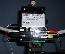
THE
FET PREAMPLIFIER
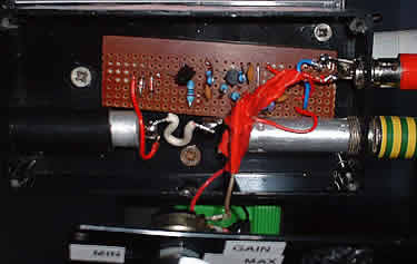 Inside
the FET preamplifier
Inside
the FET preamplifier
Larger
image of FET preamp.
Even with
a fairly large loop such as this, on quiet frequencies signals
may be heard that are just too weak to be readable. This is when
a preamplifier would be of benefit.
There
are many designs for amplifiers available, some with tuned inputs,
others with multi stages of amplification.
The idea behind this design was to keep it as simple as possible,
as my construction skills are not the best. I found a design by
Lyle, K0LR which had a tuned input stage and allowed various antennas
to be connected.
As this will only be used with the loop, I omitted the switching
circuit and as the loop will provide a tuned input stage, that
was also removed.
The result is a simple, high gain amplifier that really does improve
the performance of the loop. Being an FET design, it is low noise
(not that that is much of a problem for the listener in a suburban
environment!) and it tends not to overload in the presence of
strong signals. Obviously the quality of the receiver that you
use will determine how much gain you can use before overload etc.
sets in.
In the original design, I opted to use a switch for high/low gain
control but found this to be of little use. This design uses a
10k ohm variable resistor in parallel with R5 which allows the
gain to be varied continuously from minimum to maximum. Hence
the layout etc. is not as neat as it was originally!
The amplifier can be built on a small piece of strip board, the
layout is not critical but some care should be taken to keep lead
lengths fairly short as some problems may be encountered at high
gain levels. Current consumption is around 8mA at 12 volts, so
a small pp3 type battery could be used.
One thing to note is that the preamplifier is not bypassed if
the supply voltage is removed, which means that the loop will
appear very deaf if the preamp is left in circuit and not switched
on (hence there is no power switch). As I use the preamp all the
time, I attach the power supply when I want to listen. I use my
shack 13.8v PSU to power the preamp and have experienced no problems
at all.
CONCLUSION
I have been
using this loop for well over a year now and never cease to be
impressed by it’s performance.
The directional/nulling properties really become apparent when
listening to NDB (Non Directional Beacons) below MW, several on
the same frequency can be heard as the loop is turned.
After two years of use, I made a few improvements and modifications
(like the variable gain control and MW/LW switching). My loop
now covers the range 196-2345kHz in four switched ranges.
The range below 350kHz is taken care of by the addition of a ferrite
bar assembly from an old portable radio. I used the MW coil which
is switched in series with the main winding, and connected the
coupling winding of the ferrite bar in parallel with the coupling
turn of the main loop. This gives additional signal pick up at
the lower frequency range, but the sensitivity is no where near
as great as if a dedicated LW loop were used.
Testing against my other antennas, the loop is two S points stronger
on the BBC R4 198kHz transmission (with preamp at minimum gain).
If the gain of the preamp is increased to maximum, the loop is
better by six S points.
Where the loop really scores is in the MW band, where it works
best and signals that are S9 on the loop quite often are inaudible
on my other antennas.
ACTIVE SHORTWAVE ANTENNA
As an aside,
quite by accident, I discovered that the loop also makes a pretty
impressive active antenna for the SW bands. It is so good that
it rivals my dedicated HF antennas.
Tuning around on the SSB portion of 80m, I have heard East Coast
North Americans on my loop as loud as they are on my vertical.
I also logged Jack VE1ZZ on 1.8MHz CW at 579.
As I have no other antenna that works properly on top band, a
true comparison is difficult but I can say that I couldn’t hear
him on the other antennas.
The only disadvantage about using the loop as an active antenna
on the HF bands is that it does tend to pick up a fair amount
of electrical noise, and of course above 2MHz, the directional
properties pretty much disappear. That said, if you have antenna
restrictions then this could be a way to hear some interesting
stations without upsetting anyone.
The reason it works well as an active antenna is that the coupling
loop is the only part of the antenna that is actually connected
to the preamplifier (the main winding/tuning become obsolete and
play no part in the action of the antenna above 3MHz), so the
actual antenna length used is only about 7 feet (i.e. the circumference
of the loop).
If anyone builds this loop, I would be interested to see
how it compares to other loops, in particular commercial loops
like the Kiwa.
Sean
D. Gilbert,
G4UCJ
Telephone: +44 (0) 1908 281521
You may also download a full Hula
Loop PDF file from this web site.
|