|
Click on drawing
for larger image.
Rotatable Flag Antenna
by Larry
Molitor - W7IUV
Published
with permission; more on W7IUV's
home page
email w7iuv@arrl.net
The
"Flag" and "Pennant" antennas optimized and publicized by K6SE
on the topband reflector show great promise for those of us who
live on less than full section farms. While the Pennant is easier
to build, the Flag is symmetrical and therefor adaptable to a
rotatable configuration.
This design is presented only as a suggestion; one form of construction
of many possible choices. This design, like most of this writers
designs, was an iterative process. (I broke a lot of stuff before
this one stayed up!) Most of the design compromises centered around
free or cheap material. If cost was no object, this thing would
look a lot different.
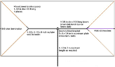
The choice
of boom material was easy; a friend had some chain link fence
top rail laying in his horse pasture. I volunteered to clean it
up for him. I wanted to use bamboo for the spreaders, but none
could be found for free or even cheap.
Several materials were experimented with before settling on wooden
clothes poles. This material is almost as light as bamboo and
is readily available in most lumber yards and home improvement
stores. It's also pretty sturdy; I dropped the thing trying to
put it up by myself and nothing broke!
The spreaders were attached to the boom with square steel tubing
welded to the ends of the boom. The tubing formed nice "sockets"
for the wood poles to slip into. One through bolt holds it in
place.
See drawing
for details.
If welding is not your thing, consider making a spreader mounting
plate from a square piece of aluminum about 12x12x1/4 inch. Drill
for U-bolts in appropriate places.
The insulator for the feed point is fabricated from polycarbonate
sheet (Lexan). Acrylic could be substituted.
See drawing
for details.
The transformer is just glued on. Mount a TV type F connector
on a small bracket. F connectors are real cheap and great when
using RG-59/U or RG-6/U 75 ohm coax. If you need to weatherproof
it, paint the whole business with PVC pipe cement, several coats,
and spray with black Krylon paint.
The insulator for the termination resistor is made the same way.
As
you may recall, the top and bottom wires are exactly 29 feet long.
The two vertical sections are exactly 14 feet long, with the insulators
at the 7 foot points.
Cut the two wires to length, each 43 feet long plus what you need
to attach to the insulators at each end. Mark the points where
the bends are made. Attach the marked points to the poles while
pulling taught. You may have to juggle the attachment points to
get it all to line up correctly. I used a staple gun to make temporary
attachments, and went back after it was all square and made permanent
attachments.
The transformer
is a topic requiring a whole paper by itself. It is necessary
to use an "isolation" type transformer rather than the more familiar
bifilar wound un-un or autotransformer type.
I started with a FT50-43 core with 7 turns of #29 AWG for the
primary, and 28 turns of #29 AWG for the secondary. The primary
and secondary windings separated as much as possible on the core.
Although that worked OK, I was wanting to experiment a bit and
wound up with a Amidon BN73-202 binocular core with three turns
for a primary and 12 turns for a secondary winding. This transformer
was patterned after a W8JI suggested design.
Flags
and Pennants have about 35 dB or so of signal loss compared
to your TX antenna, so some installations may need a "preamplifier".
Here is a schematic
of an amplifier that I have used for a number of years.
It's based on a CATV transistor and gives pretty good IMD
performance and a gain of about 20 dB. I'm working on one that's
a bit better, but don't want to publish that design until I've
had a chance to check it out on the air.
For more
information, see K3KY's Flag
and Pennant Antenna Compendium.
|