|
T2FD -- The Forgotten
Antenna
By Guy
Atkins
If a survey
were taken of all shortwave DXers to find the antennas they
use, I suspect the majority would be found using the random wire.
Next In popularity would likely be the commercially available
sloper antennas and trap dipole.
However,
an antenna's popularity does not necessarily reflect excellent
performance. While being simple and inexpensive to erect, the
randomwire is susceptible to electrical noise, and presents a
wide range of impedance to the receiver, depending on received
frequency.
The terminated.
tilted, folded dipole (T2FD) is a little known antenna that performs
excellently. Compact in size compared to a halfwave dipole
(approx. 67 feet long at 60 meters), the T2FD provides signal
gain, wide frequency coverage, and exceptionally low noise characteristics.
An early
discussion of the T2FD appeared in the June 1949 issue of QST,
a popular magazine for radio amateurs. A more recent article on
the T2FD appeared in the May 1984 73 Magazine.
The World
Radio Television Handbook for 1988 gave a brief description and
diagram of the T2FD, and that year's WRTH Newsletter provided
additional construction information. Further details were given
in the 1989 WRTH. However, some misleading and incomplete information
is given in these WRTH sources, which this article will later
clarify.
DESIGN
Some have
called the T2FD a "squashed rhombic" antenna. It does bear
some design similarities to the nonresonant rhombic, but
theoretically it is admittedly inferior. However, the T2FD performs
well in a modest amount of space, while a rhombic antenna can
be immense virtually impractical at all but the
highest SWBC bands.
The T2FD
is essentially a closed loop design with the element ends folded
back and joined by a noninductive resistor (see figure below).
The feed line can be 300 to 600 ohm twinlead or open line.
Because twinlead
and open line can be affected by nearby metallic objets (downspouts,
metal window frames etc.), a better feed line is coaxia1 cable
connected to an impedance transformer (balun).
The T2FD
has a characteristic 5 or 6 to l frequency ratio, which means
that it works effectively from its lowend design frequency
up to 5 or 6 times that frequency. For instance, the T2FD which
I use is designed for optimum performance at 4.9 MHz, but can
operate up to the 2529 MHz range. In practice this antenna
aIso works satisfactorily down to the 75 90 meter tropical
bands, but not as well as a dipole or delta loop designed for
75 or 90 meters.
PERFORMANCE
The United
States Navy conducted extensive transmitting and receiving
tests of a single T2FD antenna in the late 1940s at Long Beach,
California. They employed a Model TCC Navy I kW transmitter, with
a frequency range from 2.0 to 18.0 MHz. After a year of use on
all frequencies the T2FD was found to be superior to individual
antennas on the various bands. The other antennas were removed
from the Long Beach site affair the tests.
Similar results
during the same period were experienced by the Kyushu Electric
Communications Bureau of Japan. Their experiments indicated that
the terminated tilted folded dipole was superior to the "zepp''
and halfwave dipole types previously used. They noted wideband
characteristics, and the T2FD gave a 4 to 8 dB signal increase
at their various receiver site
My experience
has shown the T2FD to be a fine performer when only a single
shortwave receiving antenna can be erected, due to its wideband
nature. It also has the advantage of electrical noise rejection
(to a degree) compared to a random wire or even a dipole.
THE
TERMINATING RESISTOR
According
to the QST articles mentioned, the value of the terminating
resistor is rather critical. Its value depends on the feedpoint
impedance, and is normally above it. For instance, if 300 ohm
feed line is used (or 75 ohm coax into a 41 balun) the correct
termination value is 390 ohms. For 600 ohm feed line, a 650 ohm
value is best. If a 450 ohm feed line is in use, the correct resistor
would be in the vicinity of 500 ohms. I have not discovered why
the optimum terminating resistance is higher than the feedpoint
impedance, nor do I know of a formula for calculating this relationship.
The terminating
resistance becomes more critical as the feedpoint impedance is
lowered. With lines of lower impedance (including a directly connected
50 ohm coaxial cable), the value is critical within about 5 ohms.
(The QST articles did not state an exact recommended value when
using a low impedance line.)
The WRTH
editions give the erroneous impression that T2FD antennas require
a 500 ohm resistor and a 10:1 balun transformer, used with 50
ohm coax cable. This is not the case, although these values will
work fine if you have the 10:1 balun available (normally hard
to come by). A T2FD built with 75 ohm coax (RG59
or RG6), a common 4:1 balun, and a 390 ohm terminating resistor
is recommended.
The resistor
used must not be a wirewound type, its inductance
would affect performance to a substantial degree. A carbon resistor
of 1/2 to 1 watt in size is perfect (for a receive only T2FD).
The WRTH Newsletter in 1988 said that the wire for a T2FD must
be made of pure copper between 3mm and 5mm thick In reality, the
exact tbickness and type of wire have very little bearing on the
T2FDs performance for receiving. Your main consideration will
be wire strength, regardless of diameter.
CONSTRUCTION
TIPS
A T2FD takes more hardware to construct than a typical dipole.
Maintaining a uniform spacing between the parallel wires, as well
as sturdiness, are the primary considerations. My first attempt
at a T2FD selfdestructed when the antenna was hoisted into
the air. I underestimated tbe strain the wires would be under.
My current T2FD has been in use for over 11/2 years, and
was built with 14 gauge stranded, colddrawn copperwire.
The spacers
or spreader bars ean be fashioned from 5/8" (minimum) diameter
wood dowels, or even acrylic rod if available. Drill appropriate
sized holes at eacb end of the spreader bar for the wire to pass
through. The spreaders should be secured to the wires so that
they do not slide; one method is to "jumper" each spreader end
with a short piece of stiff wire and solder to the antenna wire.
It is essential
that you encase the terminating resistor inside a plastic cylinder
or other support, and weatherproof the assembly. Be positive that
the resistor will not receive the strain from the wires.
I prefer
to use eyelet bolts on the end spreader bars for tbe antenna wire
to pass through. An alternative would be some type of rod or strong,
small diameter tubing cut to the length of dimension "B". The
wire would simply thread through the rod.
Most amateur
radio supply stores sell 4:1 baluns tbat only need a wrap of "Coax
Seal" around the connections to be totally waterproof. The type
with a coax connector that will accept a PL259 plug is perfect.
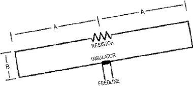
The
diagram on the following page illustrates this type of construction,
using the commonly available 4:1 balun, 390 ohm resistor, and
75 ohm RG59 coaxial cable.
On the following page is a comparison
of a 60 meterband T2FD, a 500 ft. longwire and a 50 ft. random
wire antenna.
©
Copyright worldwide by Proceedings
and author.
Easier with Inverted
Tilted Vee
Andreé Knott, DD3LY
Email comment, 18 April 2002
I built an "inverted tilted vee" antenna for my QRL with
two 250 Ohm resistors at each end and a 50:450 Ohm homemade Guanella
BalUn at the top.
This antenna is not very different to a T2FD at all as well as to
the WRTH recommendation.
My antenna has 60m legs, spreaded 60 degerees, the apex was only
8m high. VSWR less than 2 from 3 to 30 MHz and great reports.
I think the WRTH recommendation is OK and easy homebuilt too, with
the small exception that one should use a resistor which is about
20% higher than the output impedance of the transformer.
|